Tutorial
![]() >
Tutorial
>
Tutorial
The vibration map file has the extension '.vbm'.
It consists of subsections starting with '%' as follows:
%name
%authors
%date
%references
%description
%numbers
%structure
%structure residues
%sites on
%sites off
%sites type
%dihedral
%map interaction
%map param
%map dihedral
%map coupling
All of the above sections are not mandatory. The author of vbm files can select any sections necessary for his own vbm file. Also, any of the sections can be repeated any number of times. In that case, from the point of a new section, the contents of the previous sections with the same title will become no longer valid. The contents followed by "#" character are regarded as comments. Comments can be a whole line or part of a line starting with "#". Comments can be located anywhere in the file. A section can consists only of comments if necessary.
The followings are explanations for each section.
-
%name
Name of the map. Any character string on a single line. -
%authors
List of authors of this map. One person per line. Affiliation or email can be added after the name. -
%date
Date of creation of the map file. Ex) Nov. 11, 2018. -
%references
Reference papers. One paper per line. -
%description
Some description here. A version number of the file can be assigned for the author's convenience. -
%numbers
Three numbers on a single line: number of atoms, number of interaction sites on atomic sites, and the number of interaction sites off atomic sites. For example,
6 3 20
This example represents that there are 6 atoms in the molecule and 3 interaction sites on atomic sites and 20 interaction sites off atomic sites. -
%structure
Format of this section is
N atom x y z
Here N is a sequential integer, 'atom' is the name of the atom and x, y, z are Cartesian coordinates. The following is an example:
1	N                  0.00000000    0.00000000    1.42494300
2	C                  0.00000000    0.00000000    0.28940900
3	C                  0.00000000    0.00000000   -1.17937000
4	H                  0.00000000    1.01838300   -1.54494500
5	H                  0.88194600   -0.50919200   -1.54494500
6	H                 -0.88194600   -0.50919200   -1.54494500
-
%structure residues
This section can be used instead of %structure for the case of proteins or peptides. The format of this section is
N resname
Here N is a sequential integer followed by the name of a residue. For example,
   1	ALA
   2	GLY
   3	ALA
-
%sites on
This section consists of a list of integers denoting the atomic sites:
   1	n1
   2	n2
   3	n2
For example,
   1	4
   2	6
   3	8
This means the three interaction sites are located on the first, second, and third atomic sites
defined in the %structure section. -
%site off
In this section, each line starts with an integer or one of 'd0', 'd1', 'd2', d3'. The lines starting with 'd0', 'd1', d2', or 'd3' are to define a local coordinate system. The lines starting with zero or negative integer are to define reference sites to be used to define other interaction sites. The lines starting with positive integers are to define the interaction sites which are off atomic sites. . The numbering of the off-atom interaction sites starting with a positive number begins not from 1 but from n+1, where n is the number of interaction sites defined in the '%sites on' section. The lines starting with an integer has either an integer or the character 'b' as a second element.
(1)When the second element is 'b', the format is as follows:N b J K [r1]
Here, 'b' denotes that this line is to define an interaction site located on the bond connecting the atom J and the atom K. When the optional parameter r1 is absent, the interaction site is located on the exact middle of the bond and when r1 is given, the r1 denotes the ratio of the distance between interaction site and the atom J to the distance between the atom J and the atom K.
(2) The lines starting with 'd0', 'd1', 'd2', 'd3' define local coordinate system where 'd0' is the position of the local origin and d1, d2, d3 are mutually perpendicular unit vectors. The format is as follows:d0 I d1 J d2 J K d3 J d2
'd0' denotes the selection of atom I as an origin to begin the definition of a molecule-fixed coordinate system. 'd1' is defined as the unit vector whose direction is the same as the position vector of atom J from the local origin defined by 'd0'. 'd2' is followed by two numbers J and K, which means that the unit vector 'd2' is in the same direction as the cross product of the position vector of atom J and the position vector of atom K. 'd3' is followed by two elements J and 'd2', which means that the unit vector 'd3' is in the same direction as the cross product of the position vector of atom J and the vector 'd2'. In the definition of the unit vectors 'd2' and 'd3', the vectors are with respect to the site defined by 'd0'. The definition of 'd0' and 'd1' involves a single element and that of 'd2' and 'd3' involves two elements. In this way the local coordinate system is defined using only the atomic position vectors given in the 'structure' section. These definition of d0, d1, d2, d3 can occur any number of times within the section to redefine the local coordinate system. Note that the position of the origin denoted by 'd0' is only used to define the vectors d1, d2, d3 and will not be used further. When an off-atom interaction site is defined, a new origin will be given each time.
(3) The line starting with a positive integer N denotes the definition of off-atomic interaction sites The format is as follows:N I r1 r2 r3
Here, 'I' denotes the index of the atom to be used as the position of the origin for the unit vector d1, d2, d3. The three real numbers r1, r2, r3 are the coefficients in the expression r1*d1 + r2*d2 + r3*d3 which represent the relative position of the interaction site from the position of the atom I. The atom I should be nearest to the interaction site N so that we don't need any information other than the atom I and the three vectors d1, d2, d3 in defining the site N.
(4) There is a special case of N = 0. In this case the line begins with 0 and define a site in the format of (1) or the format of (3). And this site is not counted as an interaction site but can be used in the definition of other interaction sites. The line beginning with 0 can occur any number of time in the 'site off' section. For example,
   0      b      1      2
   1      0      0.0    0.7     0.7
   0      b      2      3
   2      0      0.0    0.7     0.7
The first two lines define the interaction site 1 which is defined as the vector 0.0*d1 + 0.7*d2 + 0.7*d3 from the site 0 which is defined by the first line as the midpoint of the bond connecting the atom 1 and the atom 2. And then the third line redefines the site 0 as the midpoint of the bond connecting the atom 2 and the atom 3. Then the fourth line uses this site 0 to define another interaction site.
(5) Sites with negative N is also possible and treated in the same way as the site 0. You can define a site with negative numbering when you do not want a site 0 to be overwritten by redefinition of another site 0. The sites with zero or negative numbering can be defined in any order and will not be counted as an actual interaction site.
The following is an example with explaining comments:
7      b      3      4      # define bond type points
8      b      3      5
9      b      3      6
d0     2      # define local orientation vectors.
d1     1
d2     1      4
d3     1      d2
10     1      0.70000000  0.00000000  0.00000000
11     1      0.00000000  0.00000000  0.70000000
12     1      0.00000000  0.49497475  0.49497475
13     1      0.00000000  0.70000000  0.00000000
14     1      0.00000000  0.49497475 -0.49497475
15     1      0.00000000  0.00000000 -0.70000000
16     1      0.00000000 -0.49497475 -0.49497475
17     1      0.00000000 -0.70000000  0.00000000
18     1      0.00000000 -0.49497475  0.49497475
19     2      0.00000000  0.00000000  0.70000000
20     2      0.00000000  0.49497475  0.49497475
21     2      0.00000000  0.70000000  0.00000000
22     2      0.00000000  0.49497475 -0.49497475
23     2      0.00000000  0.00000000 -0.70000000
24     2      0.00000000 -0.49497475 -0.49497475
24     2      0.00000000 -0.70000000  0.00000000
26     2      0.00000000 -0.49497475  0.49497475
d0     2 # perhaps more orientations would be necessary if fragment is large
d1     1 # ---> possibility to redefine d1, d2, d3 and create other custom sites
d2     1      4  # ---> or possibility to define multiple auxiliary vectors,
d3     1      d2 #       and choose the current orientation of local system
-
%sites type
IThis occurs only when the structure is given by '%structure residues' instead of '%structure'. The format is three numbers and a list of atom names. The first two numbers (n and n+1) denote the residues defined in '%structure residues' section and the third number is the number of atoms to be listed from the next line. The two residues define the amide bond in between them. The list of atom names is considered as interaction sites in the amide bond defined by the two residues. For example:1 2 4 1 O 2 C 3 N 4 H
This represents that the four atoms (O, C, N, H) in the amide bond connecting the residue 1 and residue 2 defined in the '%structure residues' section are regarded as interaction sites. There is a special case that the two integers in the first line preceding the list of atoms are both zero. This case represent all the amide bond not yet defined in this section. For example,1 2 4 1 O 2 C 3 N 4 H 0 0 4 5 O 6 C 7 N 8 H
This means that the first set of five lines denotes the O, C, N, H atoms of the amide bond between the residue 1 and 2, and the second set of five lines denotes the O, C, N, H atoms of all the remaining amide bonds. For the case of peptides and proteins, the frequency map assigns excluded atoms which are usually atoms near to the interaction sites O, C, N, H of the peptide bond. The list of excluded atoms can be also given in this section using the index 'e'. Note that all the atoms in this section with number indexes and 'e' indexes will be excluded in the calculation of the perturbation giving frequency shifts. We use 'CA', 'CB', 'CC', … to denote the alpha carbon, beta carbon, gamma carbon, and so on. We use 'HA', 'HB', … to represent the hydrogen atoms bonded to CA, CB, …., respectively. We use 'N-CA' to denote the alpha carbon connected to the N atom of the peptide bond and 'C-CA' the alpha carbon connected to the C atom of the peptide bond. We use 'N1-CA' to denote the alpha carbon of the residue next to the 'N-CA' alpha carbon, 'C1-CA' the alpha carbon of the residue next to the 'C-CA' alpha carbon. As an example, consider the following peptide A (taken from the supplementary material of the paper by Reppert et al. J. Chem. Phys. 2015, 142, 125104):
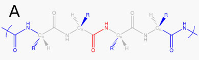
Here the red and grey atoms are to be excluded. When the 'red' CONH bond connects residue '4' and residue '5' and only the O atom of CONH is the interaction site for mapping, the content of '%site type' for peptide A will be as follows:4 5 20 1 O # interaction site and also excluded atom e C # excluded atoms from this line e N e H e N-CA e N-HA e N-O e N-C e N-N e N-H e N1-CA e N1-HA e C-CA e C-HA e C-O e C-C e C-N e C-H e C1-CA e C1-HA
-
%dihedral
This section consists of multiple lines. Each line has four integers denoting atoms to define a dihedral angle. The information of dihedral angle can be used for coupling map. For example:1 2 3 4 5 6 7 8 9 10 11 12
These three lines define three dihedral angles and will be called as dihedral angle 1, angle 2, and angle 3 and so on when 'coupling' map is defined. Alternatively, each line has only one integer followed by a letter 'N' or 'C' when the structure is defined by '%structure residues' with a list of residue names. Then this number denotes the residue having the alpha-carbon to define the phi and psi angle in peptides or proteins. For example:3 N 3 C
The letter 'N' is used to define the phi angle which is the dihedral angle of C-N-C(alpha)-C. The letter 'C' is used to define the psi angle which is the dihedral angle of N-C(alpha)-C-N, respectively. -
%map interaction
This section consists of five lines when only one kind of perturbation is present. The format is as follows:%map interaction Target property Unperturbed values of the target property Perturbation Unit of map parameters Information on the data type of map parameters [Full|Reduced]
The first line is the name of a target property. In the second line comes the unperturbed value of the target property. In the third line comes the descriptor for perturbation acting on the interaction sites, such as electrostatic potential, electric field, electric field gradient, van der Waals force, etc. The perturbation can be a product of more than one different perturbations or some power of a single perturbation or a combination of both. For example, when the perturbation is electrostatic field and potential, the following cases are some of possible examples in the third line:
electrostatic potential # linear perturbation on a site
(electrostatic potential)^2 # quadratic perturbation on a site
(electrostatic potential)*(electrostatic potential) # product of linear perturbations on two different sites.
(electrostatic potential)*(electric field) # product of two different linear perturbations on a site or two different sites.
For example, when perturbation isR_m ϕ(R_n)
, the product of position vector of mth site and electrostatic potential on nth site, the third line is written as "(position)*(electrostatic potential)". The fourth line is the unit of mapping parameter values to be given in "%map param" section. The information on the data type in the fifth line concerns the mathematical form of the mapping parameters such as scalar, vector, tensor, etc. For example, 1 for a scalar, 3 for a 3-dimensional vector, "3 3" for a 3-by-3 matrix, "3 3 3" for a tensor with triple indexes. The fifth line of "%map interaction" having "Full" or "Reduced" denotes whether the data to be given in "%map param" is in the "full" form or "reduced" form. For an example of a 3-by-3 2-rank tensor,
reduced - for a 2-rank tensor we need only 6 components:
A11,A12,A13,A22,A23,A33We always assume that the first index represents interaction sites and the rightmost index changes first when reading the data row by row.
full – for a 2-rank tensor we need 9 components:
A11,A12,A13,A21,A22,A23,A31,A32,A33
If there exist two or more sources in perturbation, the format of the set of last three lines can be repeated.
Followings is an example for the case of a single interaction site with electrostatic fields(E_x, E_y, E_z) acting as perturbation:
  %map interaction

  Frequency

  1717

  Electrostatic field

  cm^-1/(N*C^-1)

  3
The above example shows that in the mapping for frequency shift, the considered perturbation is linear terms in electric field, and the parameter values will be given in 3-dimensional vector in the '%map param' section. If we also consider perturbation having two sources, the one due to electric fields and the other due to the quadratic terms of electric fields(E_x^2, E_x E_y, E_x E_z, E_y^2, E_y E_z, E_z^2)
the additional three lines are necessary:
  %map interaction

  Frequency

  1717

  Electrostatic field              # First source of perturbation

  cm^-1/(N*C^-1)

  3

  (Electrostatic field)^2           # Second source of perturbation

  cm^-1/(N*C^-1)^2

  3   3   Reduced
Here we use 'Reduced' to specify that we will give parameters for only six elements(xx, xy, xz, yy, yz, zz)
in the"%map param" section. -
%map param
The actual parameters for mapping are given here as a multiline lists of numbers. The mapping parameters are arranged in one or multiple lines of lists of numbers in a manner freely chosen by the author of the vbm file under a single rule that the rightmost index changes first when reading the data line by line. For example the full 2-rank tensor can be represented as
A11,A12,A13,A21,A22,A23,A31,A32,A33or
A11,A12,A13or
A21,A22,A23
A31,A32,A33
A11The two sections "%map interaction" and "%map param" can occur more than one time in paired sets when multiple target properties are considered for the present chromophore molecule.
A12
A13
A21
A22
A23
A31
A32
A33
-
%map dihedral
This section describes frequency shifts due to nearest neighbor interaction of local amide oscillators in peptides and proteins. The format is such that the first two lines are as follows:N string θ_min θ_max θ_interval [θ_min θ_max θ_interval]
Here N denotes an integer referring the N-th residue defined in the "%structure reside" section. The 'string' is either 'c' or 'n' to represent the N-side or C-side amide group of –CONH-Ca-CONH-, respectively, where Ca represents the alpha carbon of N-th residue. For example,1 c
means that the map parameters are for the frequency shift of the amide group on the C-side due to nearest neighbor interaction with the N-side amide group. θ_min , θ_max, θ_interval are minimum, maximum and grid size of the phi, psi dihedral angle with respect to the alpha-carbon of the N-th residue. If these values are different between phi and psi angles, you can give all six values: θ_min , θ_max, θ_interval for phi angle and θ_min , θ_max, θ_interval for psi angle. From the third line, a matrix of parameter values is given.
For example:1 c -180 180 90 12 23 34 45 # values for (-180,-180), (-180,-90),(-180,0),(-180,90) 56 67 78 89 # values for (-90,-180), (-90,-90),(-90,0),(-90,90) 91 12 23 34 # values for (0,-180), (0,-90),(0,0),(0,90) 45 56 67 78 # values for (90,-180), (90,-90),(90,0),(90,90)
-
%map coupling
This section provides the parameters for the coupling term between two vibration modes such as the J_ij (t) term in the paper by Roy et al. (J. Chem. Phys. 2011, 135, 234507). The format is the same as "%map dihedral" with one exception that the 'string' is not necessary in the first line so that the format of the first two lines are:N θ_min θ_max θ_interval [θ_min θ_max θ_interval]
Here N denotes an integer denoting the N-th residue defined in the "%structure reside" section. θ_min , θ_max, θ_interval are minimum, maximum and grid size of the phi, psi dihedral angle with respect to the alpha-carbon of the N-th residue. From the third line, the matrix of parameters values is given.